SSTV beacon based on Raspberry Pi
Working installations
- MH Altiszti Akadémia, Szendendre, Hungary
- Frequency: 433.425 MHz
- Modulation: FM / Martin M2
- Timing: every 15 minutes
- QTH locator: JN97MP 86uv
- Coordinates: N 47° 39.28′ E 19° 04.51′
Sample images
Image received during assembly using speaker/microphone coupling | Image received from installed beacon using a cheap handheld radio and a smartphone from 12 km away | |
Software
The first prototype used PySSTV to convert images to sound. As of v0.1.9, a (2 minutes long) Martin M1 image is generated in 4. A more effective solution is in progress at UNIXSSTV, this is currently combined with PySSTV. The software pipeline can be seen below, source code can be found in the rpi-sstv GitHub repository.raspistill --(BMP image)-> PySSTV --(freq+time tuples)-> UNIXSSTV --(raw samples)-> sox
BMP was chosen since it wouldn't make sense compressing an image (wasting CPU cycles) right before parsing it in another component, and discarding the image forever. PySSTV is used for generating frequency-time tuples (e.g. 1500 Hz for 10 msec, then 2000 Hz for 25 msec, ...) as it's fast enough and it's easy to use PIL to manipulate the image, which in our case consists of resizing it and putting the callsign (HA5KDR) in the top left part of the image. UNIXSSTV performs the parts which are not that complicated, but would be too time consuming in pure Python in a constrained environment as the Raspberry Pi, and SoX (more precisely play) is used to divert the samples towards the audio output.
To avoid screwing up the SD card, by default, every part of the FS is either mounted in read-only mode (things like /home and /usr) or uses a ramdisk (things like /tmp and logs). The beacon is activated periodically using cron; even though the Raspberry Pi doesn't have a real-time clock (RTC), it can measure the time since it booted, so if configured to run every n minutes, it will do that, but it will not be synchronized to any clock.
Mounting the Raspberry Pi
The Raspberry Pi is mounted using two screws to the metal plate inside the case.


Mounting the camera
The Raspberry Pi camera is mounted to the metal plate inside the case using screws and a floppy disk cut in half and put back together using hot glue.


Connecting the transceiver and the RPi
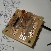
The bridge to the right and with its schematics below makes three connections possible:
- it exposes the Raspberry Pi serial console to a 6-pin header compatible with the USB TTL Serial cable, using a voltage divider, so the device can be accessed without network connectivity
- it connects the audio output of the Raspberry Pi to the microphone input of the transceiver
- it makes possible for the Raspberry Pi to switch the transceiver into transmit mode by putting GPIO 18 into high state (there could be a resistor between the GPIO and the LED, but the actual LED used didn't require one)
RS-232 level translation (serial console)
The voltage divider makes sure that voltage on the serial receive pin of the Raspberry Pi is 3.3 volts or lower. The other direction requires less attention as 3.3 volts are still above the 2.5 volts compare level used by the 5 volts FTDI cable.Audio output
As it turned out the levels matched perfectly, we found it best to turn the volume to the maximum on the Raspberry Pi. Don't forget to select the appropriate output device if you have HDMI connected!Transmit mode
Transmit mode can be switched using an NPN transistor connected to GPIO 18 (pin 12), for example using the following Python code (based on the openmicros example).$ sudo python >>> import RPi.GPIO as GPIO >>> GPIO.setmode(GPIO.BCM) >>> GPIO.setup(18, GPIO.OUT) >>> GPIO.output(18, True)
Remote operation
 The final placement of the Raspberry Pi requires to place the radio 10-15 meters away from the transceiver, and a UTP cable is used to transmit signal, TX control and power. The wire assignment is the following:
| wire | purpose | Raspberry Pi |
| orange | +5V power supply | GPIO 1-2 |
| orange-white | transceiver PTT/TX | GPIO 6 |
| green | transceiver audio signal | 3.5 mm TRS jack |
| green-white | transceiver audio signal GND | GPIO 3 |
| blue | UART TX | GPIO 4 |
| blue-white | UART GND | GPIO 3 |
| brown | UART RX | GPIO 5 |
| brown-white | UART GND | GPIO 3 |
Future plans / TODO
- install more cameras around the city
- and in other cities (countries?)
- synchronize them to send images over a single frequency
- using RTC?
- listening into each others' signals? what about timeouts?
- since the resolution of the cam is much better than SSTV, it could simulate panning
- SSDV
- add 2-3 seconds of silence after and before sending the image
- add (enable) FSKID
- handle pitch dark night
- system info
- long exposure